WORLDWIDE

SPK Product
Home > SPK Product > Frequency Controlled Product (SPK / Epson) > Quartz crystal SMD DIP Cylinder > Crystal Charateristics

Specification
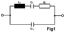
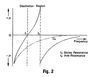
The oscillating mass of the quartz crystal corresponds to the Motional inductance L1 while the elasticity of the oscillating body is represented by the Motional capacity C1.
The values of the Motional capacity C1 are very small compared with the capacities normally used for oscillating circuits in communications engineering and can be calculated for the 'AT' cut as follows:
C1(PF)=0.22 X A(m2) X F(Hz)/1670
Where A= area of the electrode
F= resonant Frequency
The C1 value can be changed for a particular resonant frequency by varying the electrode area. The range of variation of the electrode area depends on the diameter of the quartz element.Where A= area of the electrode
F= resonant Frequency
The static parallel capacity C0 is the capacity between the vacuum-deposited metal electrodes and quartz material as a dielectric and we have.
C0(PF)=40.4 X A(m2) X F(Hz)/1670+0.8(PF)
L1(H)=4.22 X 104 X (1670)3/F3(Hz)/A(m3)
L1(H)=4.22 X 104 X (1670)3/F3(Hz)/A(m3)


TEMPERATURE COEFFICIENT
Temperature coefficient is frequency stability or deviation with timperature change.
Temperature coefficient is expressed in parts per millions, change of plus or minus percentage over the operating temperature ranges.
The mode of vibration, the plane of the plate in relation to the axis of the quartz, the dimensions of the plate and the harmonics determine the temperature coefficient.
LOAD CAPACITANCE CL
The load capacity is the sum of the capacity of the crystal sock-et or any other parasitic capacitance across the crystal in oscillator.
Load capacitance, CL is the effective capacitance of the oscillation circuit as viewed from both ends of the crystal units.(shown in Fig. 3)
CL is the capacitance value comprising the combined capacitance of capacitor, and equivalent capacitance components resulting from the phase lag, Miller's effect, etc., within the semiconductor.
In the electrical equivalent oscillation circuit (Fig. 4), operating frequency, f0 can be expressed by the following equation.

Where fs = series resonance frequency.
r = C0/ C1(capacitance ratio)
r = C0/ C1(capacitance ratio)
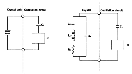
Fig. 3 Equivalent Circuit of a Crystal Oscillator I
Fig. 4 Equivalent Circuit of a Crystal Oscillator II
Fig. 4 Equivalent Circuit of a Crystal Oscillator II
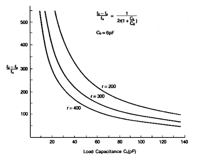
Fig. 5 Load Capacitance Characteristic
Fig. 5 shows an example of the load capacitance Characteristic calculated by equation. As can be seen from the figure, the rate of operating frequency change due to change in CL is high where CL is small. The rate of operating frequency change due to change in CL is also high when the capacitance ratio is small.In most cases the quartz crystal is operated with a trimmer load capacity in order to be able to adjust the manufacturing tolerances.
RESISTANCE AND Q FACTOR
Resistance is the equivalent impedance of the quartz resonator and it determines Q factor of quartz crystal. High crystal Q's are obtained by reducing mechanical and acoustic energy losses which is equivalent to R1.
vThe crystal Q is related to the series resonance frequency fs the motional inductance L1, and the equivalent series resistance R1.

SPURIOUS MODES
Spurious modes, which mean unwanted modes, are actually in-harmonic modes of vibration of the quartz plate. Since spurious modes are inherent in every crystal resonator, they are suppressed by special design technique.
Typical spurious specifications are 6dB below the desired mode of oscillations but they are more highly suppressed upon customer's request.
DRIVE LEVEL
The drive level normally referenced in milliwatts is the power dissipated in the crystal's equivalent resistance.
Drive level should be the minimum necessary to begin and main-tain crystal oscillation, to assure optimum performance and stability.
Excessive drive can result in breakage of the crystal element, excessive frequency drift, and poor aging characteristic.
FREQUENCY TOLERANCE
Frequency tolerance is the amount of frequency deviation (plus or minus) from the desired operating frequency at a specific tem-perature.
Accuracy requirement for crystal tolerance is expressed in per-centage. (see Fig. 6).
AGING
Aging of a quartz crystal is a general term applied to any change in parameters of crystal unit taking place over a period of time.
In order not to suffer severe aging the circuit should be designed with drive level kept at absolute minimum.
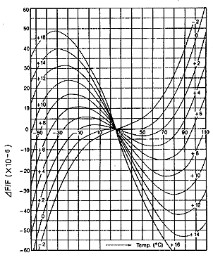
Fig. 6 AT-Cut Frequency-Temperature Characteristics
Application
Terminal Strength
| *Lead pulling | test | |
| Conditions | Load | 907.2gram |
| Direction | To the downward | |
| Duration of applied force | 5 seconds | |
| Results | There should be no distortion in appearance | |
| *Lead bending | test | |
| Conditions | Load | 453.6 gram |
| Bending angle | 90°C to normal position | |
| Rate of bending | 3 seconds in each cycle | |
| Results | There should be no distortion in appearance. | |
| Conditions | Dipping in solder (230°C ±5°C) for 5 seconds |
| Results | More than 95% of surface being tested should be coated uniformly with solder. |
| Conditions | Frequency | 10~55Hz |
| Amplitude | 0.762mm | |
| Sweep | 1.0 minute | |
| Duration | 2 hours | |
| Results | Frequency and wave from of tested products must remain within specifications. | |
| Conditions | Method of drop | Natural drop |
| Dropping floor | Hard wood board | |
| Height | 75 cm | |
| Number of drops | 3 times | |
| Results | Frequency and wave from of tested products must remain within specifications. | |
*Temperature test
| * Temperature | cycling test | |
| Conditions | Steps of cycle | 1)At -55°C, 30 minutes |
| 2)At +25°C, 10~15 minutes | ||
| 2)At +85°C, 30 minutes | ||
| 2)At +25°C, 10~15 minutes | ||
| Number of drops | 3 times | |
| Results | Frequency and wave from of tested products must remain within specifications. | |
| Conditions | Temperature | T(H) + 125°C, T(L) -55°C |
| Exposure time at | 5 minutes | |
| emperature | ||
| extremes | ||
| Number of cycles | 3 times | |
| Results | Frequency and wave from of tested products must remain within specifications. | |
| Conditions | Temperature | -20°C ± 2°C |
| Length of test | 96 hours | |
| Results | There should be no stain on surfce of products. Frequency and wave from of tested products must remain within specifications. |
|
| Conditions | Temperature | +85°C ± 2°C |
| Length of test | 96 hours | |
| Results | Deviation of frequency must be less than 3 ppm (±0.0003%) | |
| Conditions | Temperature | +40°C ± 2°C |
| Relative humidity | 90~95% | |
| Length of test | 96 hours | |
| Results | 1)Insulation resistance must be 500 Mohm/100 minimum Vdc. 2) Resistance and wave form must remain within spevification |
|
| Conditions | Helium | |
| Results | less than 2X10⁻⁸ Atm cc/sec | |


